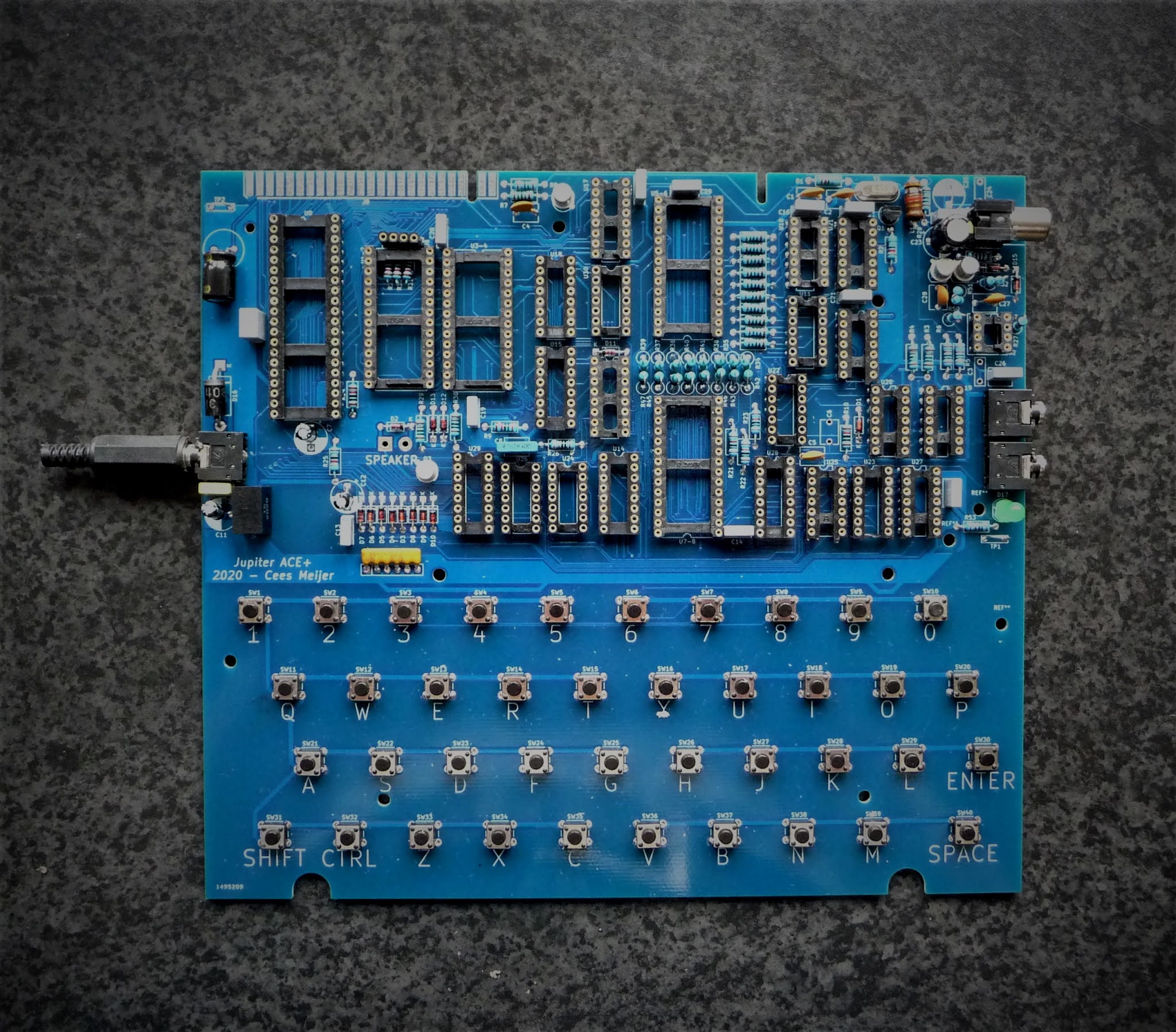
After half a day of soldering, the board looks like this:
Everything fits like a charm, and it really starts to look like a
Jupiter ACE. So it's time to start testing, and carefully insert all
chips.
Step 1: Check what is + and - on the power connector. It turns out
the Tip is ground, and the sleeve is +. Found myself a leftover power
supply (12VDC/1.4A) and mounted the 3.5 mm jack plug. Once connected
the LED goes green ! This is always a good start. After that I measured
the supply voltage on all main chips like the Z80 and some of the 74
series. All seems well.
So I first mount U23 74HC86, which is part of the oscillator, so now we should the 6.5 MHz on pin 8.
Which does not happen. There is a clear oscillator signal (with the right frequency) on pin 9, but its simply not big enough:
The signal gets bigger if I replace R2 with a 470K, just enough to get the signal on pin 8 going:
Still
looks a bit wacky, but I think that's also a limitation of my
oscilloscope which has a maximum sampling rate of 25 MHz so there are
only 4 samples per cycle.
Inserting U9: This is the clock signal divider, so there should be a clock on pin3 of U9:
Well,
at least it starts looking like a square wave now. So lets insert the
next two counters, U10 and U11. Which seems to work as well, so lets
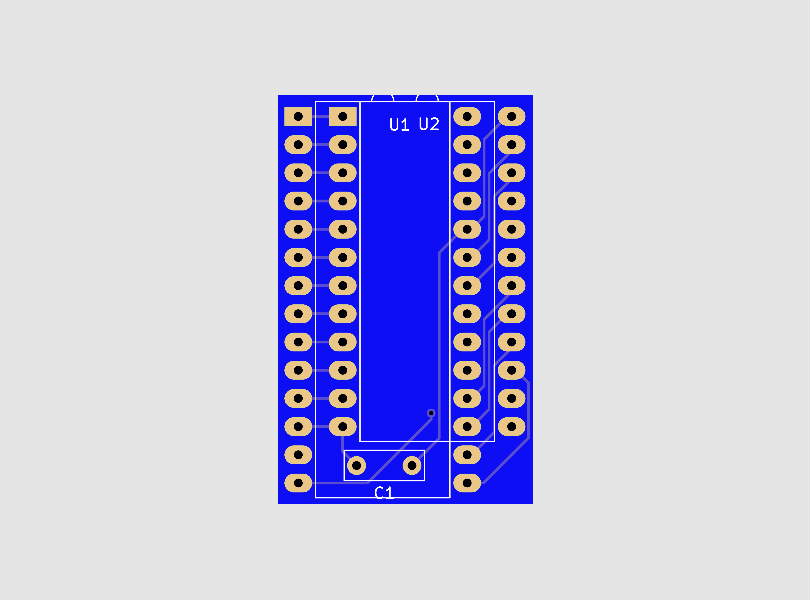
mount all other chips. All good, until I came to inserting the RAM
chips:
OH
NO !! The footprint is wrong. It took me about half a second to realize
what was wrong: I selected the DIP28 footprint for this DIP24 chip. Not
something KiCad will warn you for, after all the DIP28 has plenty of
pins for a DIP24. After about 10 minute of quiet contemplation (...) I
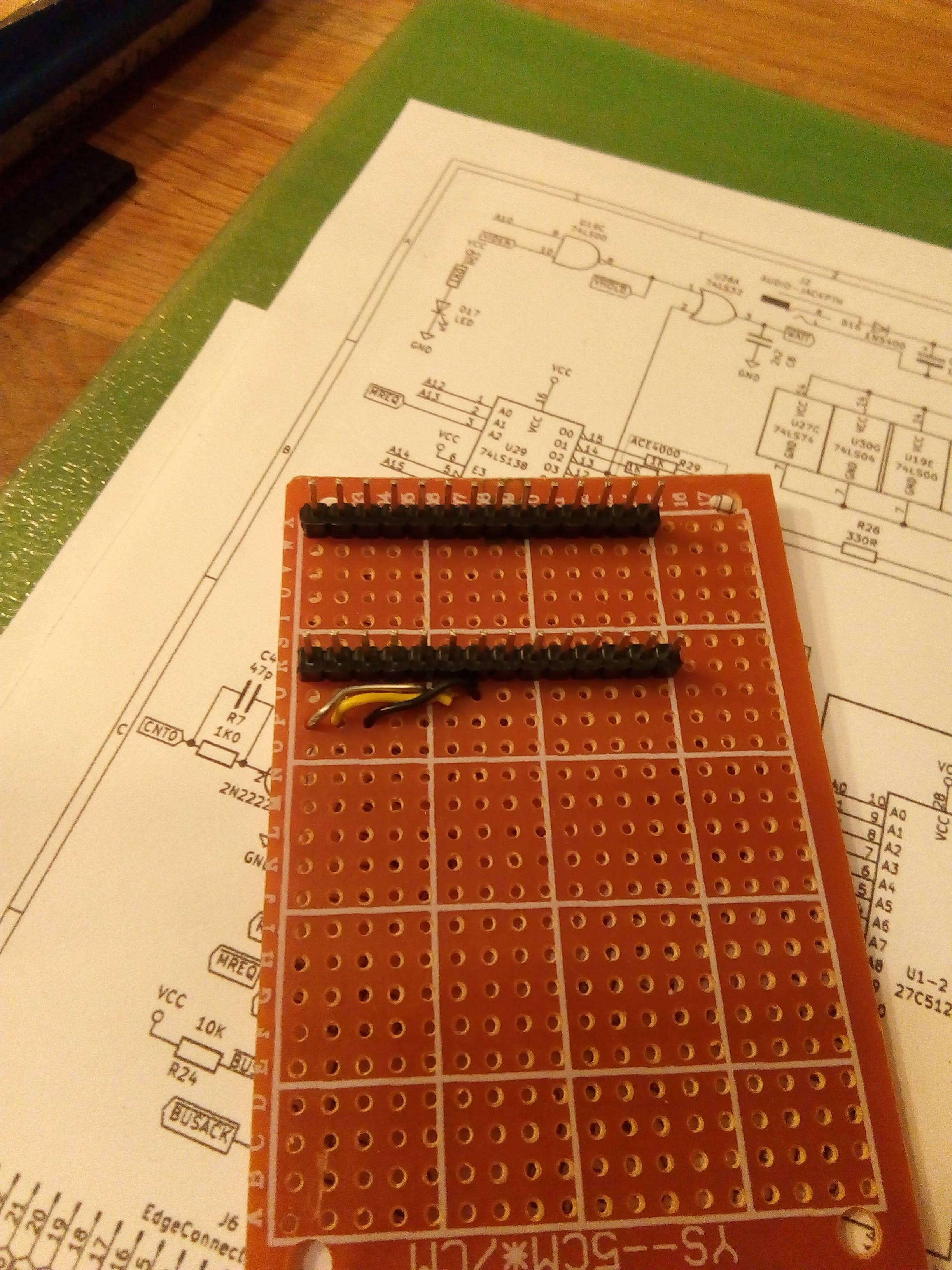
decided that I would have to make some kind of adapter with 28 pins on
one side and a 24 pin socket on the other so I could re-route all pins
from 12 and up.
Good plan, but after struggling with the first four wires, and
realizing I would have to do 3 adapters in total I gave up. Opened KiCad
again and designed an adapter PCB in about 30 minutes. Checked with the
PCB manufacturer and found that it would cost €19,- to have 15 pcs
manufactured.
So we'll have to wait another week until these boards arrive and the testing can continue.
After drawing the schematic and switching to the PCB design, the first thing I did was to arrange all components in a similar way as on the original board. Since I did follow the slightly modified version of the schematic with different memory chips, I had to make some changes, but overall the look is similar.
Original board layout, by Grant Searle
Layout, and ratsnest lines
And so, after more than a year, (where I decided multiple times that it was just to hard and almost gave up), it is finally completely routed:
And since KiCad has a 3D display tool, I can now compare my version to the original:
Since I have not been able to find a decent 3D drawing of the Jupiter
ACE housing I created this myself in DesignSpark Mechanical.
Since I do not own one to take measurements from I collected as much
photos as possible, preferably from the sides and top. The only fixed
measures I had were those of the PCB, so I used that as the basis. Then
I used placed the photos on different layers and scaled the 3D model
until it fits the images.
What I overlooked in the first place was that the housing of the ACE
is significantly larger than that of a ZX-80, which I previously printed
successfully. So I had to split the model into printable parts.
And once assembled, the top section looks a lot like the original.
Since, as mentioned in the Intro, I will probably never own a real Jupiter ACE I decided to go for the next best thing,which is building a replica. This has been done before, and the super accurate replication of the original PCB by Grant Searle is probably the best example. The schematics were redrawn later by Bodo Wenzel in ORCAD, and a modified version was made by Isidro Nuñez Blanco De Arenas.
Both builds were done 2003-2006 ( which shows if you look at the design
of their websites), and things have changed a bit since then. PCB
manufacturing is much cheaper now, and it's also easier to create custom
plastic parts. Because what's lacking in all these rebuilds is the
actual housing, which to me is a huge part of the charm of this machine.
And using a 3D printer it cannot be too hard to replicate this.
The Housing
To my surprise there are also no 3D models available , apart from the 'mini Jupiter ACE', which obviously it too inaccurate to use as a basis for a real housing.
So I started out to do this myself, using my favourite 3D modelling software: 'DesignSpark Mechanical'
(DSM). I used Grant's PCB layout, made it into a .png image and
imported that into DSM. Since the drawing includes millimetre marks on
the edge it was easy to scale it to exactly 100%.
The Keys
That's
a hard one. Getting a custom made rubber key-mat is beyond my financial
capacity so that's not an option. I'll try to make them using my 3D
printer. The main problem here is to get the text on the keys. I
considered printing this on adhesive film and just stick it on top of
the key. Then I thought I could also print the keys in white, with the
text sticking out. Then if I spray painted them black and sand the top
it would reveal the text again.
Looks great in my 3D software !. But how would it turn out in reality ?
The PCB
Though
it's possible to create the exact PCB replica using Grant Searle's PCB
foils, that is not what I wanted. I did want to make some minor changes
on the EPROM and RAM connections, and use standard mini switches for the
keyboard. Also if the PCBs have to be made by a cheap Chinese shop,
it's essential to have Gerber files. So, all in all a good incentive to
replicate the schematics again, but now in KiCad.
For years KiCad has been a bit troublesome to use, but over the last
few years it has improved significantly and is now a serious EDA
package. It's free, open source and multi-platform so it is becoming the
de-facto standard for all open-source hardware projects.